Wavefront sensing
Defocus Phase Diversity
- The defocus wavefront sensor
- The distorted diffraction grating
- Obtaining the wavefront
- Experimental data
- References
Generalised Phase Diversity
Introduction
Since the birth of modern Adaptive Optics (AO) in 1953 [1] wavefront sensors have played an important role in the design of AO systems. Wavefront sensing provides the means to measure the shape of an optical wavefront or, in the case of a closed-loop AO system, the deviation of the wavefront from the diffraction-limited case [2]. Depending on the design, wavefront sensors may be used either to generate a signal related to the wavefront deformation, or to provide a full reconstruction of the wavefront shape. In the closed-loop case one seeks to minimise the error signal through manipulation of the wavefront by a corrective element. Full reconstruction of the wavefront is more time consuming, but is sometimes necessary. In metrology applications the shape of the wavefront may represent the shape of a physical surface under test.
There are a vast array of different types of wavefront sensors in use today, this background information is limited to the type of wavefront sensor that we deal with most commonly in our research - the phase diversity wavefront sensor.
For an overview of a number of different wavefront sensors; from historically important techniques to the sensors in common use today, you can download our review paper using the link below:
H.I.Campbell, and A.H. Greenaway, Wavefront Sensing: From Historical Roots to the State-of-the-Art, in Astronomy with High Contrast Imaging III: Instrumental Techniques, Modelling and Data Processing, edited by M. Carbillet, A. Ferrari, and C. Aime, EAS Publication Series Volume 22, p. 165-185, 2006 (ISBN 2868839029). PDF
back to top
Defocus Phase Diversity
The defocus wavefront sensor
Phase-Diversity is a phase retrieval method that makes comparisons between two defocused images of the object. Phase diversity is usually implemented in the image plane but may equally well be symmetrically placed about the pupil plane, in which case the algorithm becomes essentially the same as the wavefront curvature algorithm [3]. Figure 1 depicts two spatially separated planes symmetrically placed about the pupil plane. It is in these planes that the defocused images are obtained:
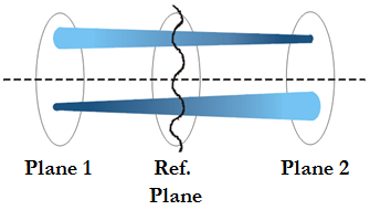
Figure 1: Diagram showing two spatially separated planes symmetrically placed about the wavefront under reconstruction.
Regions of the wavefront that are locally concave at the first plane will converge as they propagate towards the second plane thus forming a smaller, brighter spot at that point on the second plane. The opposite is true for portions that are locally convex at the first plane [4].
back to top
The distorted diffraction grating
Blanchard et al have shown that by using a distorted diffraction grating multiple object planes may be imaged by a single camera [5]. The grating is quadratically distorted (qd) so that each diffraction order represents a different focal length.
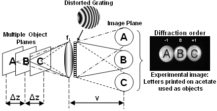
Figure 2: Use of a qd-grating and lens combination for imaging multiple object planes onto a single image plane (left). An example image of multi-plane imaging in action. (right)
The qd diffraction grating is combined with a lens and produces images of two spatially separated planes either side of the input pupil. The plane separation and the image locations are determined by the properties of the grating. In our most recent research projects we have employed this technique to provide real-time 3D imaging of live-cells for biological and medical applications.
In a generalised phase diversity wavefront sensor we would be considering using aberration functions other than defocus to convolve the input wavefront.
back to top
Obtaining the wavefront
The defocus wavefront sensor convolves the input wavefront with a defocus phase function (chosen for its ranging properties). Intensity measurements are made about the pupil plane, using a diffraction grating to capture the source image and the phase diverse data in the same detection plane. By looking at the difference between the defocused images an approximation to the axial intensity may be formed.
This approximation may then be used to solve the Intensity Transport Equation (ITE):

The ITE, as shown above (rhs), contains a curvature and a slope term. If we assume that the illumination intensity [Iz(r)] is uniform and so the slope term vanishes and the equation simplifies to:
This may then be solved using the approximate axial intensity and a Greens function solution to obtain the wavefront [6]:

back to top
Experimental data
Figure 3: Images seen by the CCD camera. Each picture shows a different aberration a) Defocus b) Astigmatism c) Coma d) Trefoil e) Spherical Aberration [4]
Figure 3 shows some example images obtained using this method. One advantage of this method is that the aberrations in the image are easily recognisable by the size, shape and intensity of these images. QinetiQ developed the wavefront sensor and data analysis software. Their interests lie in the use of this method for military ranging applications of extended scenes.
back to top
References
- Babcock, H.W., The Possibility of Compensating Astronomical Seeing. Publications of the Astronomical Society of the Pacific, 1953. 65(386): p. 229-236.
- Greenaway, A. and J. Burnett, Technology Tracking: Industrial and Medical Applications of Adaptive Optics. 2004.Institute of Physics Publishing Ltd
- F. Roddier, Curvature sensing and compensation: a new concept in adaptive optics, Appl. Opt., 27(7), p.1223-1225, 1988.
- P.M. Blanchard, et al., Phase-diversity wave-front sensing with a distorted diffraction grating, Appl. Opt., 39(35),p.6649-6655, 2000.
- P.M. Blanchard and A.H. Greenaway, Simultaneous multiplane imaging with a distorted diffraction grating, Appl. Opt., 38(32), p.6692-6699, 1999.
- S.C. Woods and A.H. Greenaway, Wave-front sensing by use of a Green's function solution to the intensity transport equation, JOSA A, 20(3), p.508-12, 2003.
back to top
Generalised Phase Diversity
Limitations of the defocus wavefront sensor
Phase retrieval using the defocus wavefront sensor relies on solution of the differential Intensity Transport Equation (ITE). One such solution, using a Greens function, imposes several restraints on the nature of the wavefront to be reconstructed [1]. These are as follows:
- The wavefront phase reconstructed must be everywhere continuous within the pupil.
- The derivative of the wavefront phase must be everywhere continuous within the pupil.
- The wavefront reconstruction requires computing effort and occasions delay, whereas it may be possible to derive a signal that can drive the wavefront modulator directly from the wavefront sensor data.
These first two are important because they potentially exclude the use of pixilated liquid crystal wavefront modulators that offer one of the most attractive options for low-voltage, low-cost, low-volume modulators. The third restriction reduces the frequency with which the AO loop can be closed compared to use as a null sensor [2].
In previous research programs we have investigated the use of alternative phase diversity functions (i.e. other than defocus) for operation as a null wavefront sensor (a sensor which gives zero output for a plane wave or non-distorted input but which will generate an error signal when the input wavefront is aberrated).
There are many applications that would benefit from a null sensor that is able to cope with scintillated and discontinuous wavefronts. One example is in polishing where it would be of great use to be able to monitor the shape of the surface being polished, in real time. This would involve laser illumination of rough surfaces, which would produce speckle (scintillation) patterns. It would also be useful to be able to image silicon circuitry and wafers, which by their design are discontinuous and therefore cannot be imaged using the current method.
The Astronomy Technology Centre (a company to which HW WAF group has had many research links across various projects) are particularly concerned with telescope and instrumentation design. In telescopes the secondary mirror creates a large central obscuration of the wavefront as seen by the primary, it is therefore a scintillated wavefront. There is also a need for adaptive correction of the wavefronts from large segmented telescope mirrors, which by their nature are piece-wise discontinuous with gaps of up to 12mm between mirror segments.
Applications such as these are what motivated us to work towards developing a Generalised Phase Diversity wavefront sensor, which could in principle use defocus, but would not be limited to this as the diversity function.
back to top
Generalised phase diversity
In a Generalised Phase Diversity (GPD) wavefront sensor aberrations other than defocus are applied to the input wavefront to generate the phase diverse data. The conditions that an aberration function must satisfy to give a useful null sensor signal are outlined in the recently published theory paper in Optics Letters. Click on the link below to open a copy of the paper to learn more about the principle of GPD:
H. I. Campbell, S. Zhang, et al., Generalised Phase Diversity, Optics Letters 29(23): 2707-2709. (2004) PDF**
**This paper was published in Optics Letters and is made available as an electronic reprint with the permission of OSA. The paper can be found at the following URL on the OSA website: http://www.opticsinfobase.org/ol/abstract.cfm?uri=ol-29-23-2707. Systematic or multiple reproduction or distribution to multiple locations via electronic or other means is prohibited and is subject to penalties under law.
The error signal generated by a GPD wavefront sensor, when the diversity phase is not defocus, can not be reconstructed using the ITE and therefore altenative phase retrieval methods must be explored. This was the course of a great deal of our previous research. For more information you can see our wavefront sensing publications, or read our phase reconstruction background information.
back to top
For more information...
Generalised Phase Diversity Wavefront Sensing, PhD Thesis, H.I.Campbell, Heriot-Watt University, School of Engineering and Physical Sciences, 2006, PDF
References
- S.C. Woods and A.H. Greenaway, Wave-front sensing by use of a Green's function solution to the intensity transport equation, JOSA A, 20(3): p. 508-12, 2003.
- A.H. Greenaway, Compact Adaptive Optics Systems II (Final Report SPC 02-4089 contract order FA865-02-M4089), Heriot-Watt University: Edinburgh, 2003.
back to top
Resources
In this section you'll find background information for our research interests (past and present) and useful links to other sites.